[Programa] Potenciómetro
Objectivo:
Utilizar o ESP32-C6-DevKitM-1 para ler valor de tensão de saída de um potenciómetro.
Lista de material:
- ESP32-C6-DevKitM-1
- Breadboards
- Potenciómetro de 10kΩ
- Fios de ligação
- Cabo USB micro

Contextualização:
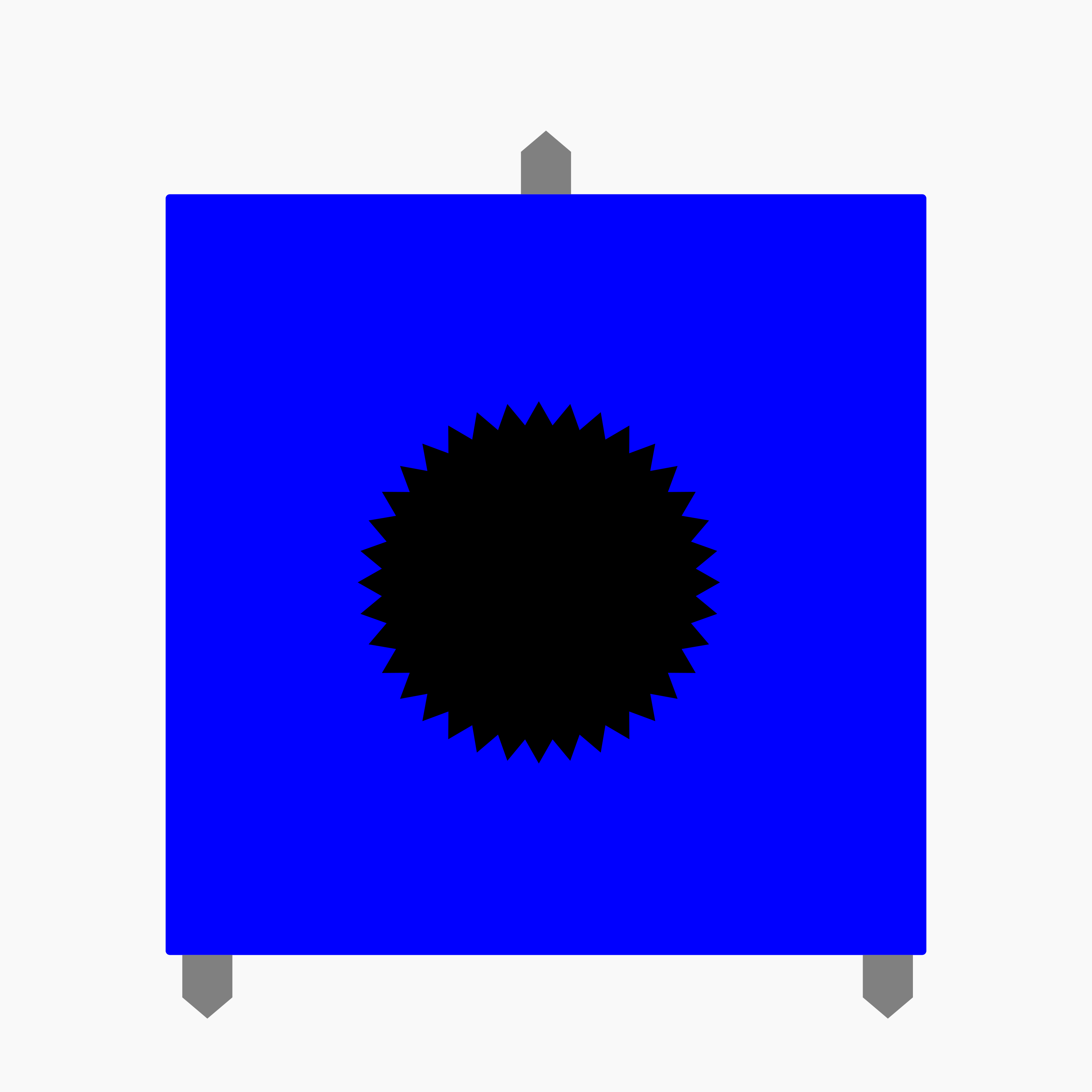
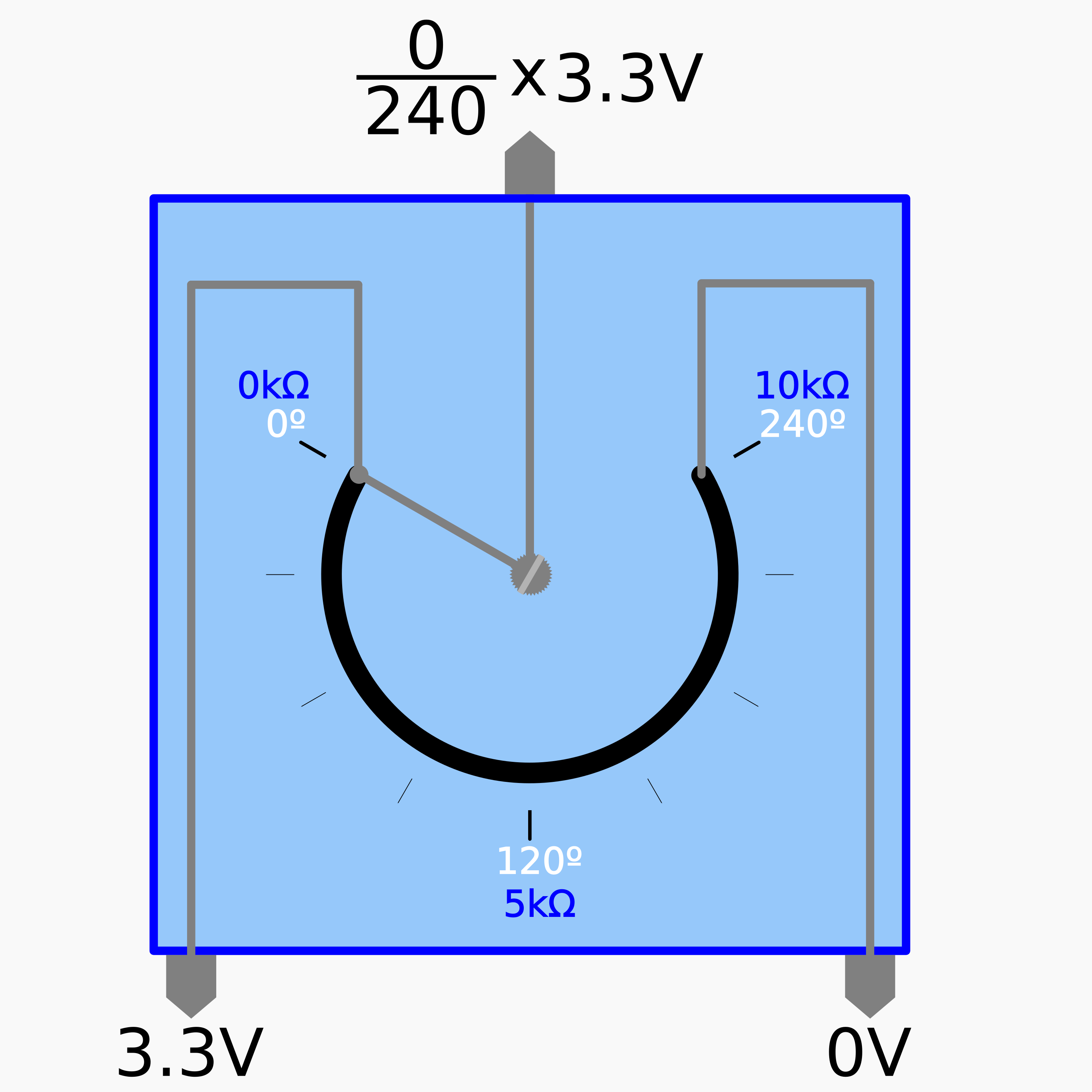
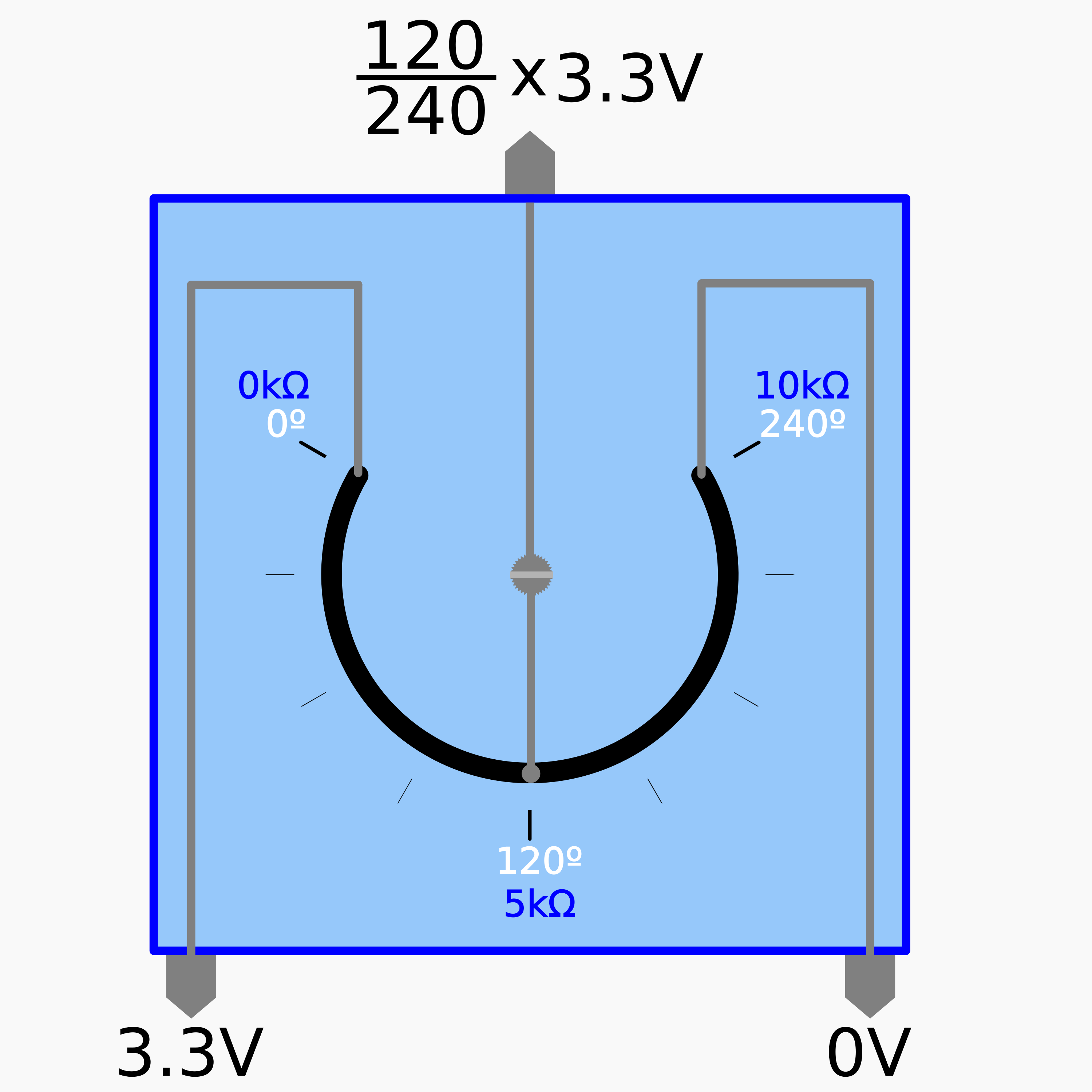
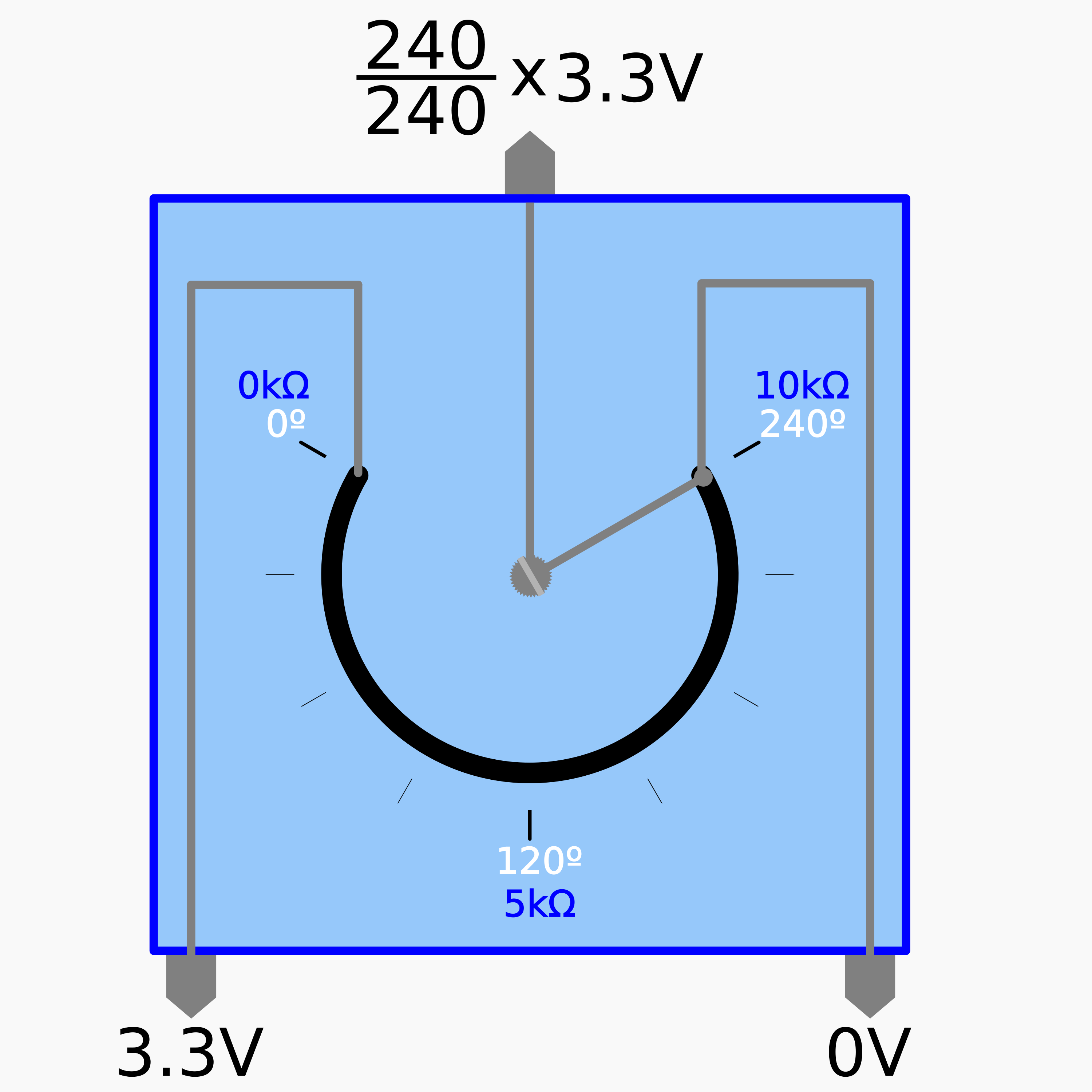
Um potenciómetro é um componente eletrónico que incorpora uma resistência elétrica ajustável [5].
Potenciómetro
Um potenciómetro possui tipicamente três terminais incluindo um contacto ajustável, deslizante ou rotativo, que forma um divisor de tensão ajustável [5].
 |
 |
 |
 |
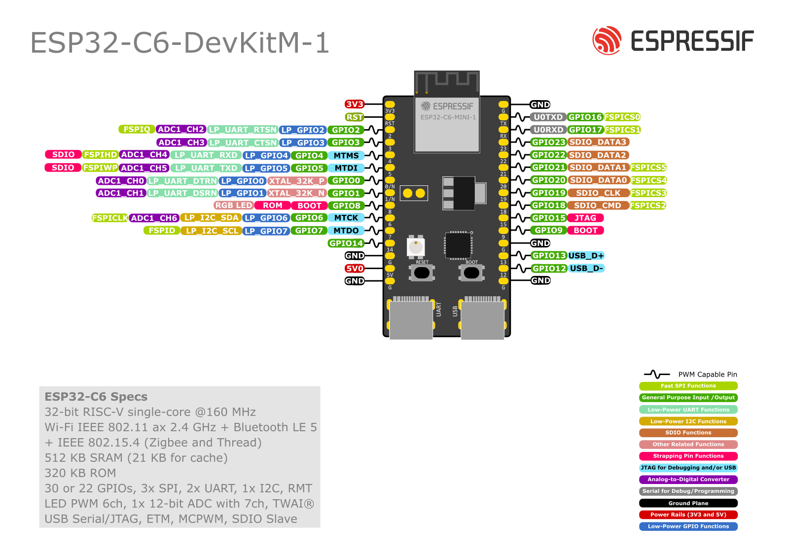
ESP32-C6-DevKitM-1
Apesar de se aconselhar a consulta da página do fabricante sobre o kit ESP32-C6-DevKitM-1 é possível considerar que em determinadas situações os terminais de entrada do microcontrolador ESP32 podem converter tensão (algo como uma quantidade analógica entre 0V e 3.3V) em um valor digital inteiro entre 0 e 4095 (num total de 212=4096 representações possíveis).
Procedimento:
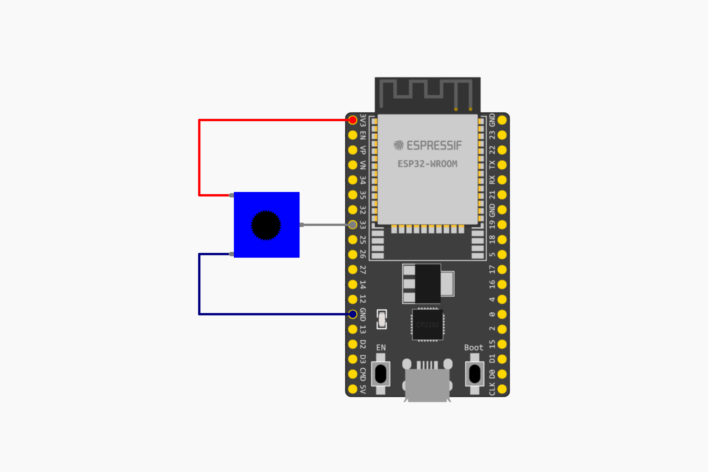
Atentando ao objetivo enunciado, e escolhendo os terminais 33 (para o terminal de saída do potenciómetro), 3.3V e o GND do ESP32 como referência deve considerar-se o seguinte circuito:
Instruções:
- Montar o circuito esquematizado anteriormente
- Ligar a placa ESP32 ao computador por via de cabo USB micro
- Abrir o IDE Arduino
- Selecionar o dispositivo ESP32 adequado
- Copiar o seguinte código
#include <Adafruit_NeoPixel.h>
#include <cmath>


// Pin and LED configuration
constexpr uint8_t LED_PIN = 8;
constexpr uint8_t NUM_LEDS = 1;

// NeoPixel object
Adafruit_NeoPixel rgbLed(NUM_LEDS, LED_PIN, NEO_GRB + NEO_KHZ800);

// Color structure
struct RGB {
    uint8_t r, g, b;
};

void setup() {
    rgbLed.begin();  // Initialize the RGB LED
    rgbLed.show();   // Turn off the LED (as it's initialized to all 0s)
    Serial.begin(115200);
}

void setColor(const RGB& color) {
    rgbLed.setPixelColor(0, rgbLed.Color(color.r, color.g, color.b));
    rgbLed.show();
}

// Convert HSV to RGB
RGB hsvToRgb(float h, float s, float v) {
    float c = v * s;
    float x = c * (1 - std::abs(std::fmod(h / 60.0, 2) - 1));
    float m = v - c;
    float r, g, b;

    if (h >= 0 && h < 60) {
        r = c, g = x, b = 0;
    } else if (h >= 60 && h < 120) {
        r = x, g = c, b = 0;
    } else if (h >= 120 && h < 180) {
        r = 0, g = c, b = x;
    } else if (h >= 180 && h < 240) {
        r = 0, g = x, b = c;
    } else if (h >= 240 && h < 300) {
        r = x, g = 0, b = c;
    } else {
        r = c, g = 0, b = x;
    }

    return {
        static_cast<uint8_t>((r + m) * 255),
        static_cast<uint8_t>((g + m) * 255),
        static_cast<uint8_t>((b + m) * 255)
    };
}

float floatMap(float x, float in_min, float in_max, float out_min, float out_max) {
	return (x - in_min) * (out_max - out_min) / (in_max - in_min) + out_min;
}

void loop() {
    constexpr unsigned long CYCLE_DURATION = 10000;  // 10 seconds for a full color cycle
    constexpr unsigned long STEPS = 1000;            // Number of steps in the cycle

    unsigned long startTime = millis();
    unsigned long currentTime;

    while (true) {
        // leitura do valor de entrada no terminal analógico GPIO33:
	      int analogValue = analogRead(2);
        Serial.println(analogValue);
	      // Normalização dos valores lidos para a tensão do potenciómetro
	      float voltage = floatMap(analogValue, 0, 4095, 0, 1.0);
        Serial.println(voltage);

        currentTime = millis();
        //float progress = static_cast<float>((currentTime - startTime) % CYCLE_DURATION) / CYCLE_DURATION;

        //float hue = progress * 360.0f;  // Hue ranges from 0 to 360
        float hue = voltage * 360.0f;  // Hue ranges from 0 to 360
        RGB color = hsvToRgb(hue, 1.0f, 1.0f);  // Full saturation and value
        //RGB color = hsvToRgb(255.0f, voltage, 1.0f);

        setColor(color);

        delay(CYCLE_DURATION / STEPS);  // Small delay for smooth transition
    }
}- Compilar e carregar o código para a placa ESP32
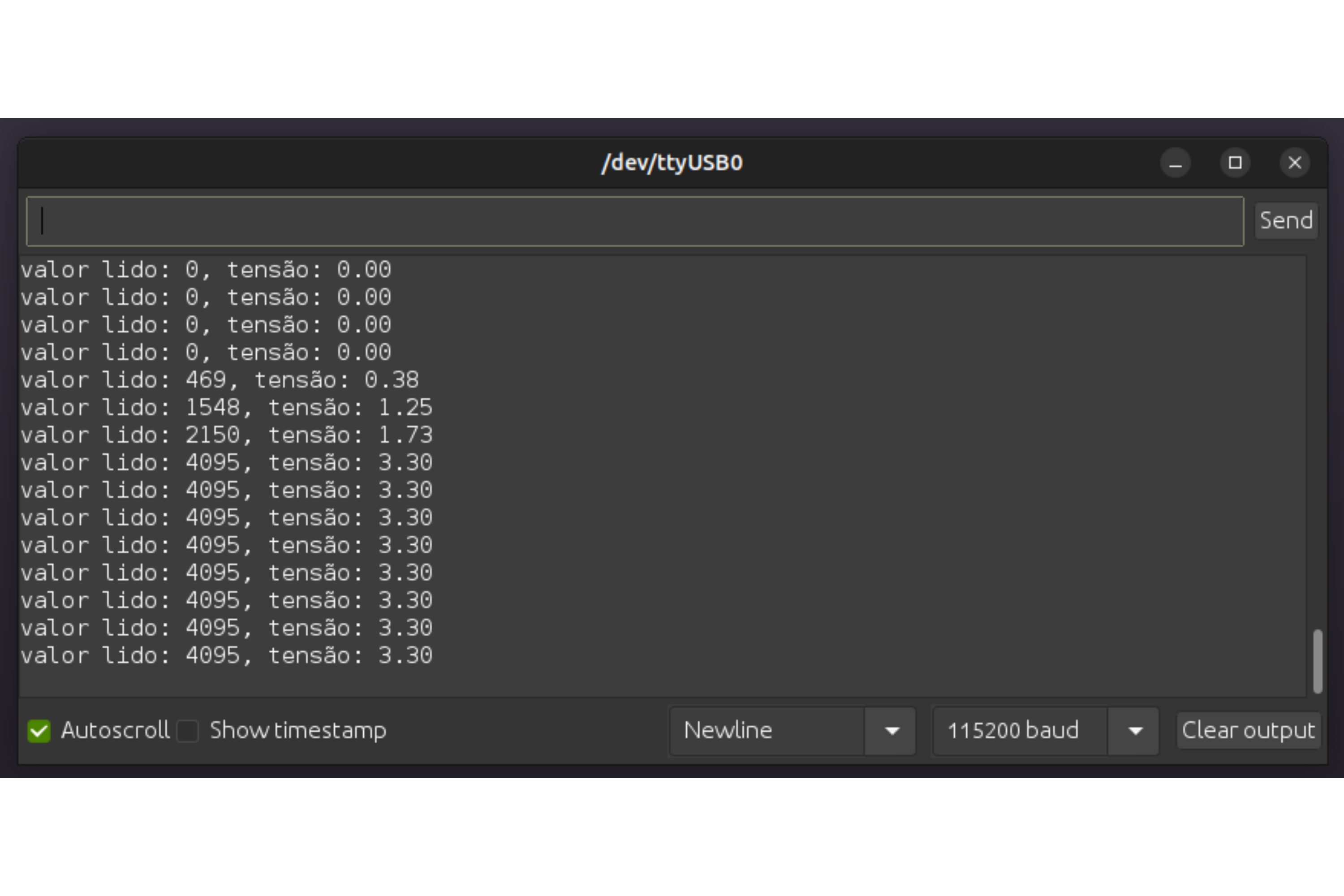
- Verificar o resultado
 |
Referências:
[1] Ltd. Espressif Systems Co. Analog to Digital Converter (ADC). url: https://docs.espressif.com/projects/esp-idf/en/release-v4.4/esp32/api-reference/peripherals/adc.html (acedido em 23/08/2023).
[2] Ltd. Espressif Systems Co. ESP32 Technical Reference Manual. Versão 5.0, pp. 631–637. url: https://www.espressif.com/sites/default/files/documentation/esp32_technical_reference_manual_en.pdf (acedido em 18/08/2023).
[3] Ltd. Espressif Systems Co. ESP32-DevKitC V4 Getting Started Guide. url: https://docs.espressif.com/projects/esp-idf/en/latest/esp32/hw-reference/esp32/get-started-devkitc.html (acedido em 18/08/2023).
[4] Paulo Menezes. Artigos de Suporte - DEEC - Kit Eletrónica - Primeiro Programa. url: https://kb.deec.uc.pt/books/deec/page/primeiro-programa (acedido em
17/08/2023).
[5]Wikipedia. Potentiometer. url: https://en.wikipedia.org/wiki/Potentiometer (acedido em 23/08/2023).